1. Preparing Files#
This is page 1 of 3 in the series on how to use the Epilog lasers in the SHED makerspace.
Preface: Operation Type#
Before we get into designing our file, we need to understand the two operating modes of a laser cutter; rastering, and vectoring. This refers to how the laser processes our file and interprets it into motion of the laser.
Raster operations are exclusively for engraving. The head of the laser moves side-to-side, turning on and off to emulate pixels. By using varying colors in our source file, we can vary how much the laser turns on, resulting in darker or lighter areas. Rasters can take a long time, since the laser has to move back-and-forth over the entire material thousands of times.
When preparing for a raster, you can use any file type. But, try to shoot for a resolution of at least 300DPI. Any lower than that, and there will be visible pixels in the final engraving.
Vector operations are primarily for cutting. When given a vector file, the laser can trace the outline, perfectly recreating the shape. When done at a high enough power this can cut through the material. You can also achieve fast engravings by running a vector operation at a lower power than cutting, although this can only engrave lines.
As the name implies, vector operations require a vector file (DXF, SVG, PDF, etc.) to work.
Tip
You can embed an image in a vector file to both engrave and cut in one job!
Preparing Files for Laser Cutting#
File preparation is one of the most important steps in laser cutting, specifically when it comes to vector-based files.
Info
The rest of this document covers sanitizing and configuring vector files to get the best laser cut. If you are just engraving an image, the image file is all you need.
Here are the 5 most important things we are going to look out for in our vectors;
Line Color#
Vector processes and orders can be set based on the color of the line. For example, I can tell the laser to cut through all red lines, but engrave all blue lines. I could also specify I want the green lines cut before the black lines.
When setting line colors, it is best to use distinct, standard colors like black, blue, red, green, yellow, etc., as opposed to R253 G103 B92.
Line Weight & Opacity#
It is important that the vector lines are all of a similar thinness, and have no transparency (100% opacity). If your software supports it, “Hairline” thickness is ideal. Otherwise, 0.1mm is a standard thickness.
Making lines thicker does result in a thicker engraving if you raster, but vector cuts and engravings are always the same thickness and follow the center of the drawn line.
Scale#
While most softwares are pretty consistent. there is no one standard for determining the scale of a vector file. What's worse, is that competing standards mean your file may only change by a small amount that is not noticeable until it is too late.
Therefore, it is recommended to draw a box of a known size around your file. Then, in the laser software, you can scale the entire design until the outer dimensions match.
Fill#
If vector lines form an enclosed area, you can fill that area with a set color. While this is fine for engraving, vector operations ignore fills. Fills can also make it hard to see hidden errors in vectors. It is recommended to keep fills turned off unless you intend to engrave them.
Stacked Lines#
One of the most common failures we see with parts exported from CAD is that there are multiple copies of the part, stacked right on top of each other. The laser cutter is not smart enough to determine and ignore these, so it will result in the laser trying to cut your part multiple times, leading to poor finishes.
Using Inkscape to Prepare Files#
Let's take a look at an example file, and prepare it for laser cutting. The file to the left is a PDF I exported from Fusion 360, I want to laser cut out that shape in the middle. If you would like to follow along, the file can be downloaded to the left.
Inkscape, the software we will use to clean this file, is a free vector editor we use a lot at the SHED. You can find it on any of our computers, or download it yourself at the link below.
Ungrouping#
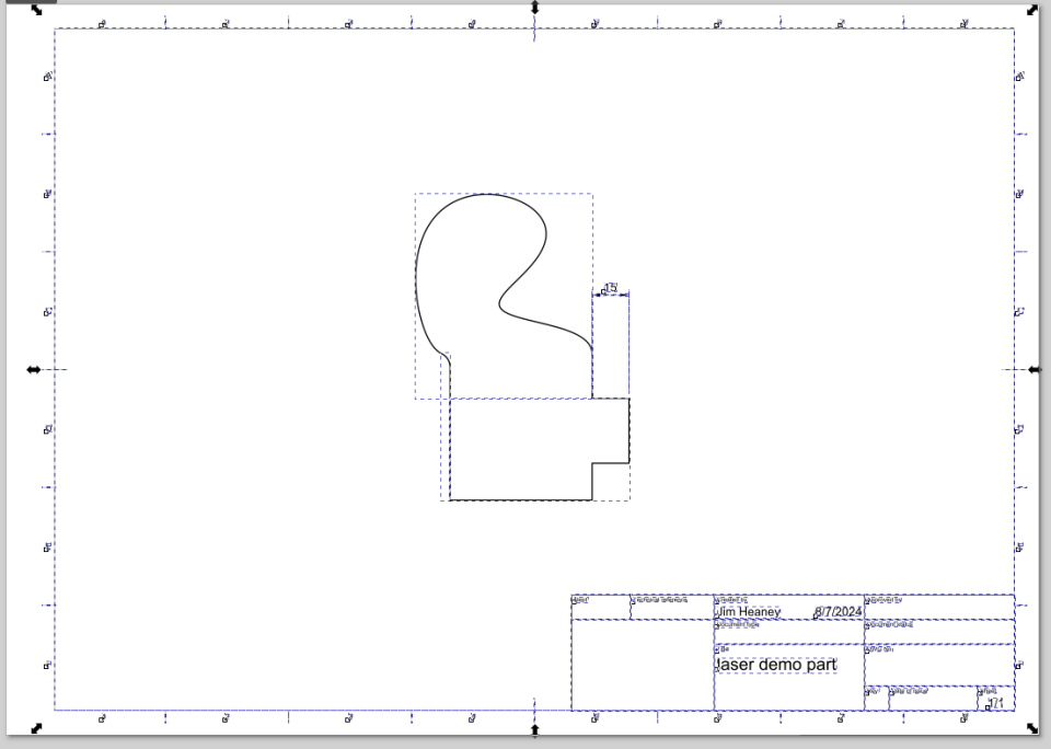
Vectors can be grouped together for ease of manipulation. The issue, though, is having everything grouped will make it harder to edit. We're first going to ungroup everything.
Select everything (Windows: CTRL+A)
Repeatedly hit the ungroup button (Windows: CTRL+SHIFT+G)
If you have fully ungrouped everything, you should see an individual selection box around every component.
Delete Unwanted Geometry#
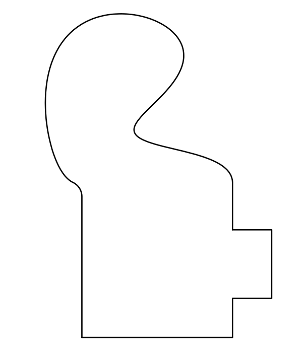 Anything in the file will be cut/engraved. In our example, we do not want the engineering drawing template cut out of our shape, nor do we want the dimension engraved on it.
We need to go through each piece of geometry we do not want, and delete it from the file until we have isolated the part we want to cut.
Add Scaling Box#
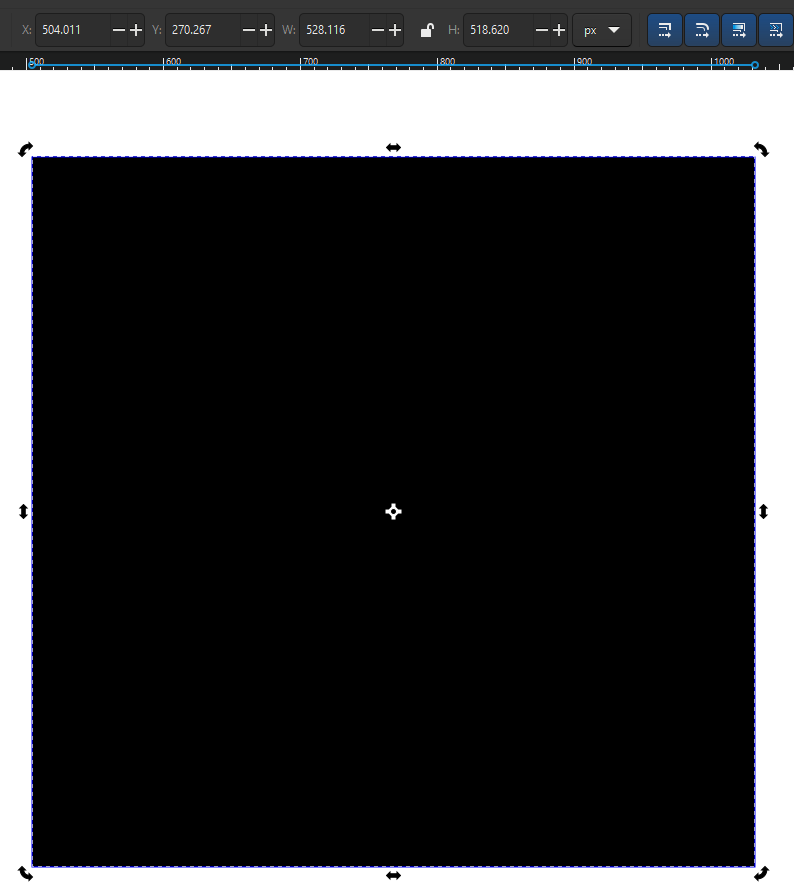 Let's now add that box we talked about earlier, to ensure the scale stays the same when we import it.
The box tool is the pink icon 4th down on the left side of the screen. Click in one corner, and drag to the other to draw a square. The box may appear as a weird color or even solid, don't worry about this.
If you select the box, at the top the dimensions will appear. The default unit is “px” (pixels), you can click on this dropdown to change to a more useful unit, like inches or millimeters.
You can then type in dimensions for this box in the “W” (width) and “H” (height) boxes. If there is a lock icon between them, the ratio is locked and changing one will adjust the other automatically. Click the lock icon to unlock it, or click the unlock icon to re-lock the aspect ratio.
Make note of what dimension you set the box to, and make sure that it fully covers your part.
Fill, Stroke, Weight, Opacity#
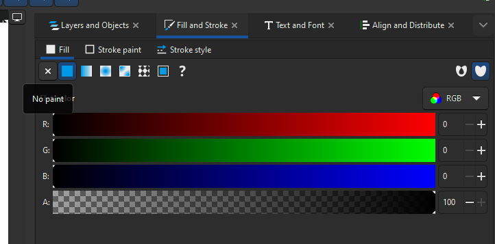 Everything related to how a vector looks is handled in one menu. Let's go through that now, and while we are at it we'll fix the box.
First, open the “Fill and Stroke” menu, under “Object”, section option down. (Windows: CTRL+SHIFT+F)
First, let's fix the box's fill. In the “Fill” tab, select the box and hit the “X” to remove the fill.
Next, let's check out the stroke color. We want our outside box to be a distinct color from the part we want to cut. It looks like that is the case by default, but if we needed to change it we can adjust the sliders in “Stroke Paint” to do so. We should also select our part and make sure it is all one consistent color.
Lastly in the “Stroke Style” tab, we can set the line width. We can select a line and change the unit to “Hairline” to set them all to hairlines.
Stacked Lines#
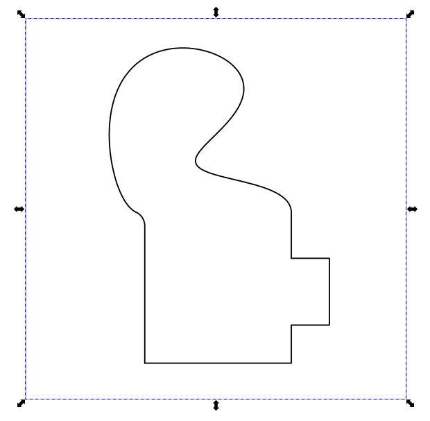 Let's quickly check for stacked lines before we are done. To do this, simply select your part and hit delete. If the part seemingly does not disappear, you've probably uncovered a second copy buried below. Continue deleting until the actual part disappears.
When the actual part disappears (either eventually or immediately) hit the undo button to restore it.
Exporting File#
Once everything is set, we can export our file as an SVG by going to File, then Save As.